EG4 Community Forum

6000xp Balancing is...
 
Notifications
Clear all

6000xp Balancing issue--how to correct?

57 Posts
6 Users
9 Reactions
1,024 Views
Posts: 26
Topic starter
(@brdfrd)
Eminent Member
Joined: 3 months ago

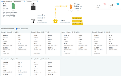
I've got a 6000xp installed, off-grid, with 4 EG4 LL-S batteries. They keep going out of balance, WAY out of balance. One battery barely discharges, and one seems to take most of the discharge.

I contacted support, through the website and they suggested switching to lead-acid mode and then charging fully, and discharging a couple time. I did the best I could, but I'm only at the off-grid cabin for 2 days, every other week. With winter here now, we're getting multiple, successive days with no sun. So, when I'm at the cabin, the only means of fully charging is a generator. This brings me to issue number 2, I can't charge at a rate greater than 1900 watts--no matter what I've set the max generator input to. So, it takes a long time to fully charge. I don't have the generator set up to automatically start yet, that'll happen on my next trip up.

I would love to figure out what I have set up wrong--or what I'm not understanding about the settings. As it is now, if I get the generator set up to automatically start, based on SOC, if I use a number like 30%, that one low battery will be at or near zero. I'll have to set the SOC trigger at something like 50-60%, which seems ridiculous--I can't use a significant amout of my battery bank capacity.

Any guideance/suggestions would be appreciated.

Thanks, Brad

Screenshot 2024 12 06 at 5.56.18 AM
Screenshot 2024 12 06 at 5.57.11 AM
56 Replies
Posts: 26
Topic starter
(@brdfrd)
Eminent Member
Joined: 3 months ago

Adding that I have the batteries installed in an EG4 6 bay battery cabinet.

Reply
11 Replies
Joel Brodeur
(@joel-brodeur)
Joined: 4 months ago

Reputable Member
Posts: 274

@brdfrd What size gen are you using?

Also, your "Generator Charge Battery Current" is currently set at 30A.  This could be what is limiting your charge rate.

You will need to balance you Max Gen Input to your Gen size - Up to 7370 for one 6000xp

Then set your "Generator Charge Battery Current" to an appropriate setting so as to not over run your gen and also to not allow enough overhead to run your cabin while charging.

If you need help figuring out the number just let us know.


JB

Reply
(@brdfrd)
Joined: 3 months ago

Eminent Member
Posts: 26

@joel-brodeur 

I'm using a WEN DF875iX. The specs say 6300 watts (running--7800 surge), on propane--generator is connected via a 240v NEMA L14-30R twist lock receptacle--so, 240v, 30A, that works out to a potential 7200 watts. I feel like the 6000xp just isn't calling for enough power.

Thanks, Brad

Any insight on the battery imbalance?

Reply
(@jlankford)
Joined: 4 months ago

Estimable Member
Posts: 135

@brdfrd 

That's 30amps of AC current, not DC. And since the sustained rate on the gen is 6,300, you should limit to 26 amps AC.

But the setting that's currently set to 30A is for DC charging current. To deliver the gen maximum of 6,300 watts to the batteries, the setting should be 112 amps  (6,300 watts divided by 56 VDC charging voltage equals 112.5 amps).

Your setting value of 30A is limiting the charging to around 1,680 watts.

Reply
Joel Brodeur
(@joel-brodeur)
Joined: 4 months ago

Reputable Member
Posts: 274

@jlankford You type faster than me.  🙂

I haven't set my Gen charge current to the maximum yet as I have always wondered what will happen if the cabin then takes a far load.  My understanding is that the loads circuit will get priority over the charge circuit.

Do you set yours at the max value?  If so, have you had any issues with the 6000xp prioritizing loads correctly?

@brdfrd Sorry no insight on the imbalance.  I have read on other posts that setting to lead acid and running a few discharge/charge cycles does seem to fix it for many people (not necessarily all of them).

I am thinking it is an Issue with the BMS calculating SOC. If you look at your cell voltages, they all appear to be in a fairly tight range, so getting the BMS to "rethink" what is full and what is empty, should help.

YMMV

Good luck and please keep us posted,

JB


Reply
(@jlankford)
Joined: 4 months ago

Estimable Member
Posts: 135

@joel-brodeur 

I'm not using a 6000xp, I have an 18Kpv. And I'm using a very small 120VAC generator through a Chargeverter to recharge batteries in the case of a long grid outage. I've set the Chargeverter to pull the maximum sustained wattage from the gen, which is only 1600w - comes out to a 26A DC charge limit on the Chargeverter.

Regarding the imbalance, I see a big difference in SOC in my battery bank, specifically one rack unit which appears to take all the discharge pulled by the inverter during EPS standby. It's common for me to have five batteries at 100% and the one at 80%. During backup operation all six units then discharge equally. So to prevent the one from going below 20% during discharge I'd have to limit the entire bank discharge to 37%. I've done several deep discharge and full recharge cycles on the system in an attempt to reset the BMS SOC references, to no effect. I'll be making a more detailed forum post about this soon...

Reply
Joel Brodeur
(@joel-brodeur)
Joined: 4 months ago

Reputable Member
Posts: 274

@jlankford Wow, and I worried about my 1% to 3% discrepancy.

I look forward to seeing your post.

JB

Reply
(@brdfrd)
Joined: 3 months ago

Eminent Member
Posts: 26

@jlankford 

Thanks very much--that wasn't clear online, in the monitor center. The little question mark links, that you would click for an explanation about the setting, all contain void javascripts. It would be really helpful if they worked--and probably reduce the number of folks contacting support.

Back to the imbalance issue. I'm thinking I need to shut the one battery off, once it charges to 100%, to force the other batteries to discharge more quickly. I'm guessing they need to "learn" to discharge?

Thanks, Brad


Reply
Joel Brodeur
(@joel-brodeur)
Joined: 4 months ago

Reputable Member
Posts: 274

@brdfrd Just for reference regarding the "?" - just over your cursor over the "?" and a help tip window shows up.  No need to click.  At least that is how it works in edge and chrome.

Regarding the turning one off, that tends to make sense to me but I am not sure.  I wonder if they all need to "learn" together.

Hopefully @Jared will chime in.

JB


Reply
(@brdfrd)
Joined: 3 months ago

Eminent Member
Posts: 26

@joel-brodeur 

Thanks--that's helpful--I've never had that pop-up. But I just waited, like 5 seconds, and it eventually does. I guess I've never waited long enough. The browser still shows a javascript void message. 

Brad

Reply
Joel Brodeur
(@joel-brodeur)
Joined: 4 months ago

Reputable Member
Posts: 274

@brdfrd The JavaScript void message indicates that by clicking the "?" nothing will happen - basically no hyperlink.  The popup is a tooltip.  A common practice but one that I wish folks wouldn't use. I am an old fart, and I prefer an actual popup window so that when I move my mouse it doesn't go away.

JB

Reply
(@jlankford)
Joined: 4 months ago

Estimable Member
Posts: 135

@brdfrd 

The 112A figure above needs to be adjusted downwards to account for the charging efficiency of the 6000xp (93%) in order to prevent pulling too much sustained power from your generator. So the math becomes...

6,300 x 93% = 5,860 watts

5,860 watts / 56VDC = 104.6 A DC

If the charging voltage is not 56 VDC, then the figure should be adjusted again.

Reply
Posts: 135
(@jlankford)
Estimable Member
Joined: 4 months ago

Following. I see similar issues using an 18Kpv and six LL-S batteries in an EG4 rack.

Reply
Jared
Posts: 247
Admin
(@jared)
Online Support
Joined: 5 months ago

Could you post a few pictures of how they are connected and the dip switch configuration?

Reply
36 Replies
(@brdfrd)
Joined: 3 months ago

Eminent Member
Posts: 26

@jared I can, in a week, when I'm back up there. However, they're all connected to the bus bars in the EG4 cabinet, using the supplied cables--the bus in turn, is connected to the inverter with 1/0 copper battery cables. Dip switches were set as directed and double checked.

The master battery is in second position down from the top, second in the third rack, third in the fourth rack, and fourth in the fifth rack--that fourth one is the one that seems to be bearing most of the discharge--it is always the lowest withing an hour of starting to discharge. The third battery may go 12 hours before it starts to discharge.

Screenshot 2024 12 06 at 5.56.18 AM


Reply
(@brdfrd)
Joined: 3 months ago

Eminent Member
Posts: 26

@jared Just realized I had this photo on my phone. Shows the dip switch configuration:

Battery 1
-
  -
  -
  -
  -
  -

Battery 2
  -
-
  -
  -
  -
  -

Battery 3
-
-
  -
  -
  -
  -

Battery 4
  -
  -
-
  -
  -
  -


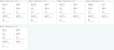
Alos, batteries drifting further apart this AM. Battery 3 (02 in the image) stayed at 93% overnight, battery 4 (03) went from 53% to 46%.

Brad

IMG 6601
Screen Shot 2024 12 07 at 7.57.02 AM
Reply
(@jlankford)
Joined: 4 months ago

Estimable Member
Posts: 135

@brdfrd 

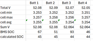
Based on your last screenshot batt data, I think you are seeing the same problem as me. In reality, the batteries are remaining in sync and balanced, but the BMS calculated SOC is drifting way off from reality. Based on the cell voltages, all four of your batteries are within 1% of SOC, and the total reported battery bank SOC of 64% is about 20% higher than reality, which is about 45%:

brdfrd data

I think these batteries are failing to update the BMS calculated SOC value when discharge currents are small. Some batteries are more sensitive than others with this current measurement threshold, and so the reported SOC values fall out of balance.

Reply
(@brdfrd)
Joined: 3 months ago

Eminent Member
Posts: 26

@jlankford Thanks. That is interesting, if it's the case. The battery gauge on the battery, as well as the info displayed on the screen all jive with the online monitor. I have noticed that the voltages have remained close, but also that the current draw, is generally higher on the low battery, and often zero on the high one.


Brad

Reply
(@jlankford)
Joined: 4 months ago

Estimable Member
Posts: 135

@brdfrd 

FYI, I have a battery bank of LL-S which is currently showing 98% (five batteries at 100%, and one at 90%). In reality, based on voltages, every battery is presently sitting at about 77% and all are equal. The batteries showing 100% always display 0.0A for discharge. I think when the current draw is small enough, the BMS ignores it both for LCD panel display and for SOC calculations.

Reply
(@brdfrd)
Joined: 3 months ago

Eminent Member
Posts: 26

@jlankford 

Please forgive my ignorance, but I thought that voltage isn't an ideal way to determine SOC, due to how these batteries were designed to discharge at a relatively flat voltage, until they're near depleted. I'm just sort of frustrated at all the technology involved here to be able to record this data and deliver remotely, if it's not reliable or accurate--or that the batteries themselves don't perform as expected.

Thanks, Brad

Reply
(@jlankford)
Joined: 4 months ago

Estimable Member
Posts: 135

@brdfrd 

You're correct that due to the flat discharge curve of LFP using voltage is not an accurate way to determine SOC, mostly between the range of 20~90%. But as a means of getting an estimate for comparing battery state as a sanity check, it's good enough. When I state my batteries are "at 77%" that's an interpolated value from a table, which is good + or - some large margin of error.

I think these batteries are performing well. Despite the weirdness with the reported SOC value I'm not a dissatisfied customer. I'm just working on characterizing this SOC behavior so I can understand what my system is doing. The equal voltages are telling us that the batteries are working in sync, which is expected because they are all interconnected by a massive bus bar. Small charge and discharge currents which are not displayed by the BMS should keep them all equal.

The next time you are on site, it would be helpful for you to switch each battery circuit breaker to OFF and let them rest at least one hour. This will isolate the batteries from each other and let them settle to a true idle voltage. Then take a new screen shot and show us how close the voltages are. Note that the batteries will continue to report BMS data to the inverter, and thus to the monitoring site, with the breakers off.


Reply
(@brdfrd)
Joined: 3 months ago

Eminent Member
Posts: 26

@jlankford 

Thanks for the thorough explanation--much appreciated. Next visit to the cabin, I'll be adding another battery, and setting up the automation for the generator because with the current weather we've been having, we can't make it 2 weeks without setting it into stand-by. We have had clouds/snow daily for the last 10 days. The trip after that we'll be moving the battery cabinet, so that'll be a good time to shut them down.

For this trip, I'll start them charging on the generator, as soon as I get there--when levels are close to the new battery, I'll add that in to charge. Once they're all at 100%, I'll start connecting the generator control module I have, and start running my mini-split to pull them all down a bit, so I can cycle them once before I leave.


Brad

Reply
Jared
Admin
(@jared)
Joined: 5 months ago

Online Support
Posts: 247

@brdfrd What lithium brand and battery protocol is being used?

Reply
(@brdfrd)
Joined: 3 months ago

Eminent Member
Posts: 26

@jared 
EG4 48v 100Ah LL-S (x4)
I had been discharging in Lead Acid mode based on advice from Tech Support. I have to switch back regularly, just to check SOC, since that doesn't show up for lead acid on the monitor site.

Brad

Reply
(@brdfrd)
Joined: 3 months ago

Eminent Member
Posts: 26

@jared 

Photo of the batteries, above, with the dipswitch info...

Reply
Jared
Admin
(@jared)
Joined: 5 months ago

Online Support
Posts: 247

@brdfrd the dip switch order is correct. Would you be able to charge the battery bank up to roughly 57.4v or until a cell hits 3.6v on each battery and then switch back to BMS communication? If CAN EG4/LUX is available, I would recommend setting the lithium brand to 1.

Reply
(@brdfrd)
Joined: 3 months ago

Eminent Member
Posts: 26

@jared 
I'm not at the cabin until this weekend. I'm going to have to put it on stand-by, remotely, tomorrow. I have 2 of the 4 batteries at 28%, and 25% now--I don't want to risk running them below 20% SOC. I will be charging them all up to 100% SOC, and adding a 5th battery Saturday--I will watch the battery voltages when I do so. Should I change from charging via SOC values, to voltage values?

I currently have the master battery connected via the CAN port

Reply
(@jlankford)
Joined: 4 months ago

Estimable Member
Posts: 135

@brdfrd 

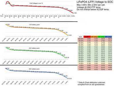
Keep an eye on your cell voltages so you don't accidentally run one or two of the batteries into the ground. With the reported SOC numbers being higher than reality, that's a possibility. Note that a min cell voltage of 3.20V is at 20%, 3.15V is 14%.

LFP Voltage Chart (DIY Solar)
Reply
(@brdfrd)
Joined: 3 months ago

Eminent Member
Posts: 26

@jlankford 

Thanks. I have 2 batteries now, at 25 and 28%, with min cell voltage at 3.206v, 3.207v, respectively. The whole system will be set to stand-by, later this evening. I've been moving to stand-by when the lowest battery hits 20%.

Reply
Jared
Admin
(@jared)
Joined: 5 months ago

Online Support
Posts: 247

@brdfrd I would set charging to based on voltage to make sure that the cells reach the overcharged warning protection.

Reply
(@brdfrd)
Joined: 3 months ago

Eminent Member
Posts: 26

@jared 
In lead acid, or lithium mode?


Reply
Jared
Admin
(@jared)
Joined: 5 months ago

Online Support
Posts: 247

@brdfrd I prefer lead-acid mode for this.

Reply
(@brdfrd)
Joined: 3 months ago

Eminent Member
Posts: 26

@jared 

The only issue with this, is that in lead acid mode, I cannot monitor SOC or remaining Ah capacity via the monitor center. Is there any issue with switching to lithium mode for a few minutes a couple times a day to check battery levels?


Brad

Reply
Jared
Admin
(@jared)
Joined: 5 months ago

Online Support
Posts: 247

@brdfrd you would only need to charge the battery bank in lead-acid mode once, until it triggers the battery overprotection warning once one cell hits around 3.6V. At that point, the SOC should automatically calibrate, and you can switch back to lithium mode.

Reply
(@brdfrd)
Joined: 3 months ago

Eminent Member
Posts: 26

@jared 

Ah---thanks.


Reply
(@brdfrd)
Joined: 3 months ago

Eminent Member
Posts: 26

@jared 

Okay, Jared--I charged them up with the generator, in lead acid mode, twice last weekend--and added a fifth battery, as number 5 in the battery bank.

The battery (number 4) that was discharging faster than the others, still is--the others have been within 1-2% of each other. In fact, in the first day after we left they satyed at 100%, while the other battery dropped to 92%. Currently I have 4 at 100%, and 1 at 77%.

These are the relevant charge settings I used:

Screenshot 2024 12 18 at 3.02.19 PM
Screenshot 2024 12 18 at 3.03.02 PM

Perhaps I didn't have those set right? I'm getting pretty frustrated because while I have 500Ah of battery, I effectively only have 80Ah I can use before I need to shut everything down. And, I can't run the mini-split because that just draws that battery down too quick. It was 20 degrees in the cabin when we got there because we had to put the system on stand-by last week due to the low battery. I'm worried about damaging the batteries.

Here's the current SOC:

Screenshot 2024 12 18 at 3.09.51 PM

Brad

Reply
(@jlankford)
Joined: 4 months ago

Estimable Member
Posts: 135

@brdfrd 

What do you think your typical power consumption is at your cabin? How many kWh per day are consumed and what would an average discharge current be?

Reply
(@brdfrd)
Joined: 3 months ago

Eminent Member
Posts: 26

@jlankford 

Well, right now, it's 1.3-1.5kWh--just running wireless internet and security cameras. That's all I dare run at the moment. Solar production has been a lot worse than expected, best day this month was 2.7kWh, but only 12.kWh for the whole month. Average discharge is 1.6-1.7kWh--sometimes a little less.

We haven't had much sun--it's our first winter there, so learning... I know we don't have enough panels--was just hoping to be able to make it 2 weeks so we could get up there every other week, before they go dead--and we would, if the freakin' batteries would balance. Next visit I should be able to finish automating the generator, which will help. But, in the current state we'll be running it often, just to keep that one battery happy.


Brad

Reply
(@brdfrd)
Joined: 3 months ago

Eminent Member
Posts: 26

@jlankford 

adding this: average continuous current discharge is 45-60 watts.

Reply
Joel Brodeur
(@joel-brodeur)
Joined: 4 months ago

Reputable Member
Posts: 274

@brdfrd Here is my experience with Auto Gen start:

The gen appears to start when the inverter shows below the set SOC Start, not when a battery hits the Set SOC Start.

From what I am seeing of you cell voltages it appears that it is a SOC interpretation issue with the BMS on bat 4.

SO, my question is:  What does the inverter say as batt SOC when you have one that is lagging behind?

Not saying this is correct and I hope that we can figure out why that one BMS is so outta whack. But it should give some peace of mind that the gen start will work, and that battery can go much lower than what its SOC is showing.

I wish there was some way of charging a battery to full (maybe using the BMS over charge protection) and then resetting the BMS to tell it that THIS is 100%.  

Hope this helps some at least with the gen part.

Fingers Crossed,

JB

Reply
(@brdfrd)
Joined: 3 months ago

Eminent Member
Posts: 26

@joel-brodeur 

Next trip to the cabin I should have the gen set up to auto start, so we'll see. I generally keep an eye on it from the online monitor center--which gives me both the individual battery SOCs, and the inverter view of total SOC--I'm definitely going to need to start it off a higher minimum SOC--to account for the one low battery--until I get this sorted out. For example, I now have 4 batteries at 100%, and one at 70%--total SOC says 94%.

Reply
(@jlankford)
Joined: 4 months ago

Estimable Member
Posts: 135

Posted by: @joel-brodeur

...

Not saying this is correct and I hope that we can figure out why that one BMS is so outta whack

...

@brdfrd

@joel-brodeur

You guys are thinking about this backwards. Instead of brdfrd having one battery that’s “outta whack”, in his low-discharge scenario he actually has one battery that’s accurate and all the other batteries are incorrect. All of his batteries are discharging together and are balanced. Look at the voltages. Look again at the rested voltages of all the batteries isolated from each other to confirm it. There’s a parable here somewhere about when one person in a crowd is in disagreement with everyone else, then it’s that one person who’s considered insane.

When looking at brdfrd’s earlier screen shot, note that the voltages of ALL the batteries near 52.10V indicate the total system SOC is estimated at 45%. Now look at the reported SOC of Batt_04 at 46%. It looks to me like Batt_04 is the only sane one in the group, which supports what I’ve been explaining here in this thread about current measurement threshold and calculated SOC. The BMS SOC calculation is simply a summing / integration function using a coulomb counter. For all of the time periods where the BMS is ignoring discharge current because it is below the 0.5A threshold, the BMS is not including that discharge energy into its integration when it calculates the total SOC. Hence all the other batteries’ SOC is reported higher than actual.

brdfrd 495 Screen Shot 2024 12 07 at 7 57 02 AM

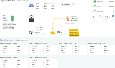
Here's a recent shot of my system. I have a known slow discharge of about 1800Wh per day. I can calculate at the time of this shot that my system SOC should be down to 85%. Only one battery shows close to that figure and the others are still showing 100%. All six batteries are discharging together and remaining in balance. I know with certainty that not only Batt_04 has been discharging. If it was the only one discharging it should be down to 10% SOC at this point since I can calculate that about 4,500 Wh total has been discharged from the system. I know from previous tests that I would recharge the system with about 4,500 Wh of energy at this point, and that all six batteries would receive an equal amount of charging energy based on the individual charging currents they will display.

batt status 20Dec2024 1500

For these slow-discharge scenarios it’s unfortunate that the SOC calculations are so misleading, but this appears to be a fact of life that EG4 cannot fix with a software change. I’m certain their 0.5A measurement threshold is reasonable based on hardware design and measurement uncertainty. They would probably need a circuit change to improve it. I know of a different LFP brand that has a 1.0A measurement threshold as stated by their engineering dept. – this is not unique to EG4.

Note that one problem this creates is when attempting to use SOC control for charging control settings. Notice in my screenshot that the total system SOC is still at 97% and 586 Ah, while in reality the actual system status is 85% SOC and 510 Ah. The steady discharge happening on my system right now is because I’m conducting a test using SOC charge control to see how long before the system will recharge my batteries again. I have the Start Charging setting at 90%. The inverter hasn’t charged in 3 days. With the current trend my actual system SOC is going to have to drop to 40%, so that Batt_04 is reporting 40%, before the reported total SOC drops to 90% and causes a recharge to start.

I already know the settings values I need, changing to Volt charge control, to cause the inverter to keep my battery bank topped up, and the inverter will add 1,800 Wh to the bank each day. I’m describing all of this because I think you’re going to have similar problems attempting to use SOC charge control in order to automate your generator charging. You’re going to need to use Volt charge control instead, and then find the Start and Stop values that will work for you to keep the charge state where you want it.

One other item to be aware of… note the BMS Limit Charge low value of 75A on my screenshot. I’ve seen that value as low as 30A. You didn’t include it, but I imagine yours is equally low. In your last screen shot showing a SOC of 100, 100, 100, 77, 100 your total system SOC is reporting at 95% and 475 Ah, so the master battery is probably limiting charging to 25 or 30 A. I have my AC charging limit set to 7.5 kW. However, in closed loop the inverter follows this BMS value and only charges at 1.6 kW etc. For me this isn’t a problem - I can wait all day charging from grid. But for you running a gen, be aware of it. For you to do what you need with generator automation and be able to charge at the capacity of your generator, you will probably have to use open loop, unless EG4 has a way for the inverter to override that BMS Limit Charge parameter.

Sorry this was a very long post. I’m characterizing this slow-discharge behavior for my own benefit right now to understand my new system. I have found that if I can understand a topic well enough to explain it to someone else, then I understand it better for myself. So, in a way, you’re serving as my therapist. Thanks for listening…


Reply
(@brdfrd)
Joined: 3 months ago

Eminent Member
Posts: 26

@jlankford 

Thanks for your thorough response. I understand what you're saying, but in one sense, I don't care which is out of whack, one battery, or the others, the voltage or SOC--I just want the damn things balanced so I have a sense of how much capacity I have left. I have a significant chunk of change invested in these and the inverter, and I just want the features they have to work well enough that I can go a couple hours without feeling like I need to check on them.

But, I see that going off the voltage, they are all pretty close--however, once they start to discharge, that one battery that the SOC always starts dropping first, and fastest, is always the lowest voltage by just a little, and also show the highest current discharge--at low loads by .5-1.5 amps, higher load 2+amps. Further, the battery that shows the highest SOC, is always the last to register any number of amps in discharge--usually 0 at low loads, often half of that registered by what I'm calling the lowest battery by SOC. And, as the SOC values between the high and low batteries grows, so does the difference in voltage between them.

I'm reluctant to extrapolate the SOC based on voltage, and then bank on that--being cautious because I don't want to tank the battery. I believe there is some difference in how they are discharging, and that 2 batteries are misbehaving, with opposing performance--ignoring the SOC. I've done as suggested by 2 different folks at EG4, and I don't see that anything has changed significantly. I am going to check on the continuity between the batteries and bus--but I'm not really expecting to learn anything there. I wiped all contact areas with denatured alcohol before assembling, and torqued to spec. Unless one of the battery cable lugs was crimped poorly, there shouldn't be any significant difference.

I am also concerned about the generator charging based on SOC, as you describe testing. As you point out, the total battery bank SOC will register a higher number than the individual batteries. I was already doing the math to try to estimate when I might need to start generator charging and it seems like 60-65% SOC, if I want to be safe--based on SOC, but not really sure exact SOC... And, if you need to do this, it'll be kicking the generator on earlier, and thus more often than I should really need with the 5 batteries--maybe I should've only bought 2--and spent the rest on propane.

Another thing to note, when I have been at the cabin, the numbers I'm seeing on monitor center are consistent with those displayed on the individual batteries. I tend to be more familiar with the monitor center, than the 6000xp display, mostly because I use it more, being away from the cabin for 2 weeks at a clip--and only being there for 2 days at a time. Plus, I haven't found the 6000XP to be very user friendly.

Right now, I have a frustrating situation where the cbin indoor temp is approaching freezing, and not having a reliable sense of the SOC, I'm reluctant to run the heat, but I'm going to have to because the temps if going to go down to around 5 degrees tonight, and it'll probably drop to 10-15 inside. The battery manuals don't recommend charging batteries below freezing--right now, they're about 33 degrees. We might actually get some sun tomorrow, but even if we have full sun, it won't offset what the mini-split will use togetthe temp up to around 40. I might just put it on standby, until I can get up there after Christmas.


Thanks, Brad

Reply
(@jlankford)
Joined: 4 months ago

Estimable Member
Posts: 135

@brdfrd 

I agree you probably don’t have a connection problem unless there’s a bad crimp somewhere. If you check for this, don’t forget the trick of measuring voltage drop across each cable while pulling a steady high current – this should give you a better measurement than trying to measure the miniscule amount of resistance across each cable.

I understand your reluctance to use voltage instead of SOC, but in this scenario voltage is the only indication that can be trusted. You’re going to drive yourself crazy trying to use SOC set points for generator control. Instead of using general voltage tables, you can determine an accurate voltage/SOC correlation for your system as follows:

The best way to know what your actual SOC was is to re-charge the system to full and measure how much energy went back into the battery bank. From that you can calculate the actual SOC at the time you began the charging cycle. Now use the data history in web monitor to see exactly what the battery voltage was just before charging was started. Look at either vBat or Vbat_Inv – they should be the same value during slow discharge. This will give you a SOC <-> Voltage data point for your system.

This doesn’t help with daily monitoring – it’s a way to characterize what is going on, learn your system behavior, and determine the comparable voltage levels for your operation. From that I think you can decide the voltage settings you can use for gen automation. Do this reverse-calculation trick for a few different SOC levels and you will learn the voltage values you can trust for your system. Here are some SOC/voltage values that I now trust for my system with six LL-S rack units:

54.1V   99%

53.1V   94%

53.0V   73%

51.3V   20%

Use your data history in the web monitor to see what the lowest vBat value has been during your typical slow-discharge use and during times when the mini-split has been cycling on and off. Use that data to decide a voltage value for your Start Gen setting to stay above that discharge level. How far above, will take some trial and error. Note that the vBat value is probably pulled down somewhat whenever the mini-split cycles on, so if you pick a Start value too high it may cause the gen to run more frequently than you wish. After you get a few automated charge cycles under your belt you can review how much energy went back into the system during each automated charge cycle and fine-tune your voltage settings accordingly. The amount of charging energy will tell you how low the actual SOC dipped before the gen started. I hope you can eventually find the settings that let you start to trust and ignore the system, regardless of the reported SOC values – that’s my objective for my system.

You can also look at the history value for MaxChgCurr to see if the BMS limit value I warned about in my previous post is going to give you problems with maximizing the generator charging power. That effect is going to waste more propane than having the charging cycles running too frequently. If in the data history you see that MaxChgCurr is too low at the time points where vBat has dropped to your desired Start Gen setpoint, then you won’t be able to charge with the generator maximum power, unless you’re using open loop.

FWIW, this inability to use SOC in slow discharge scenarios is recognized by more people than me, and it’s applicable to all LFP brands. Here’s a quote from a DIY thread:

“2 main reasons why SOC % is not accurate is that:
1: Most BMS shunts are only accurate to +-5%.
2: With small power draw from inverter, the BMS may not register that small draw. It gets worse for multiple battery packs since that current gets divided amongst all the packs. Most BMS will not register current <.500A. So when Batts are being charged or discharged at that level, the BMS's are not able to measure that current even though the cells are taking/shedding energy.”

https://diysolarforum.com/threads/tips-on-bms-balancer-optimization-and-various-discharge-curves-for-lf280k-v3.94834/#post-1270436

As I read that again, I realized this is not just a discharge problem. It sounds like you have a very small PV array right now, and with winter conditions you may often be charging with less than 200 watts, which will cause your individual SOC values to get further off track with charging currents below 0.5A. Note that in that DIY thread he also states that BMS-calculated SOC can only be trusted in systems that fully recharge their batteries to 100% every day. I’m inclined to agree with that statement.

Reply
(@jlankford)
Joined: 4 months ago

Estimable Member
Posts: 135

@brdfrd 

OK, that's what I was expecting.

My system sits in EPS standby and consumes about 1.8 kW per day from the battery. With that low current spread across six LL-S units, the per unit discharge rate is around 0.25 amp. Jared has confirmed here that the BMS current measurement threshold is 0.5 amp. So for me, all of my batteries are continuously discharging in standby while the SOC reported remains at 100%. I have one battery that appears to be a bit more sensitive with this current threshold and does report a drop in SOC.

When I have the system settings configured in a way that doesn't allow a grid-recharge to occur daily, I see a steadily growing discrepancy in SOC between by 100% units and the one that decreases to 90%, then 80, then 70, etc. In reality all six batteries are at the same SOC and resting voltage. I know this is true because when the rack is later recharged at high current, I see the exact same charging current going into each battery for exactly the same duration - all batteries accept the same amount of charging energy.

You have the same situation. At 1.5 kWh daily, your five batteries are each discharging at an average of 0.24 amps, well below the 0.5 amp threshold, and you have one battery that's a bit more sensitive to the measurement and is reporting a drop in SOC. Like you, when I added additional batteries to my rack, only the one battery continued to detect the SOC change. I find it an interesting coincidence that for both of us, the unit that detects the SOC change is ID_04. This is just a coincidence though - in my case I have moved batteries and changed the logical ID numbers and the behavior remained with the physical unit.

Reply
(@brdfrd)
Joined: 3 months ago

Eminent Member
Posts: 26

@jlankford 

Thanks. So, if I had a higher continuous draw--maybe at least 200 watts or more--the discharge may be more likely to be spread across the batteries, balanced? When I was at the cabin, running the mini split at +/- 1000 watts, that 4th battery still discharged faster, although they all discharged.


Reply
(@jlankford)
Joined: 4 months ago

Estimable Member
Posts: 135

Posted by: @brdfrd

@jlankford 

Thanks. So, if I had a higher continuous draw--maybe at least 200 watts or more--the discharge may be more likely to be spread across the batteries, balanced? When I was at the cabin, running the mini split at +/- 1000 watts, that 4th battery still discharged faster, although they all discharged.


I think the discharge is spread across the batteries regardless, but most of them are simply not measuring it.

When you say that one unit discharges faster than the others at higher loads, are you talking about SOC numbers, or discharge current? If all batteries display the same rested voltage (remember my previous suggested test), then when there's a load high enough to be registered by all batteries they should all be displaying the same discharge current +- a small margin. If you are still trying to compare SOC numbers, then unless your higher load is constant there are still going to be time periods of lower current where Batt_ID_4 is going to drop its SOC faster than the others. So, the SOC divergence would continue during the higher usage, i.e when the mini-split cycles off.

If Batt_ID_4 is really discharging faster than the others based on amperage numbers, then I would reexamine all of the battery connections, bus connections, etc. If you have an accurate meter you can measure continuity at every cable interface and confirm it's 0.0 ohms. A better check would be to pull a high steady current load from the system and measure voltage drops across each cable interface.

<edit>

Don't rely on the web monitor for comparing battery discharge current - the lag and update period is too slow. You need to be at the rack waking up each battery and looking at what its display reports.

Reply
(@jlankford)
Joined: 4 months ago

Estimable Member
Posts: 135

@brdfrd 

FWIW, here is the status of my system right now. This is exactly 36 hours after the last full charge took place. With 1,800 watts of EPS standby consumed per day, my system should be down 2,700 Wh right now, which is 8.9 % of my total capacity. Note the data shows my Batt_ID_04 is down by exactly how much its 9% contribution should be, while the others still show 100%.

It appears that Batt_ID_04 is showing me a SOC value which can be used to know my entire battery bank state. Not in all cases, but in this very slow discharge case it is. It's possible that your Batt_ID_04 is giving you a similar representation of your entire bank status, while all the other batteries' SOC values are off in the weeds. Note that my inverter is telling me I have 99% SOC and 591 Ah available, when in fact the amount is 91% and ~546 Ah. You can't depend on the totals your inverter is displaying during this slow discharge scenario.

I've spent enough time measuring and characterizing this behavior to prove what I am saying is true for my system. I've almost reached the point of understanding what is happening enough to start ignoring it. All of my batteries are working together at both low and high discharge rates. The BMS SOC calculations are very misleading, which in turn causes the inverter's total system capacity status to be misleading.

batt status 19Dec2024 1400


Reply
(@jlankford)
Joined: 4 months ago

Estimable Member
Posts: 135

Posted by: @brdfrd

@jlankford 

Thanks. So, if I had a higher continuous draw--maybe at least 200 watts or more--the discharge may be more likely to be spread across the batteries, balanced? When I was at the cabin, running the mini split at +/- 1000 watts, that 4th battery still discharged faster, although they all discharged.

Yes, that’s correct. If you start with a fully charged system, all reporting 100%, and then give it a constant 200 watt discharge load, I predict you will see all the batteries reporting nearly the same SOC as the system discharges. And it doesn’t need to be a constant discharge. It can be a random load as long as the floor doesn’t go below 200 watt. Next time at your cabin fully charge the system, find some constant 200w load you can turn on, and then let the mini-split cycle on and off as needed. I expect after a day you will be satisfied that what I’m theorizing is true.

Note that the discharge is evenly spread across all batteries even at low discharge. It's only the calculated SOC values that are not "evenly spread."


Reply
(@dannysabour)
Joined: 2 months ago

New Member
Posts: 1

@brdfrd I have 4 indoor EG4 batteries paralleled (EG4-Wallmount indoor battery -48V 280Ah - 14.3KWH). I would say these are battery banks paralleled. Using 4 6000XPs in parallel. Sadly one of the banks is draining and going out of sync so quickly. I have to manually monitor the level every day. The monitoring Software doesn't tell me the battery levels. I have to go to the battery to see it. But now I can see the issue. I think it is the S/W in the 6000XP. Yesterday I charged them all to 100%. Today they are at 59%, 78%, 78%, 76%. 

I don't think EG4 have got their act together when it comes to paralleling. The paralleled 6000XPs use an unusual amount of power to sync even in a dormant state: They use up 7% of the the 4 batteries with no load when paralleled. If 6000XPs are not paralleled. No loss on battery.

I wish EG4 would listen to the customers and fix the battery drain sync issue. I read the threads and I see people are all adapting and trying to find a solution. Very nice cutomer base. Take note EG4 please


Reply
Posts: 135
(@jlankford)
Estimable Member
Joined: 4 months ago

I looked closer at your screenshot of the battery status. i just wanted to add here that like yours, my system while the SOC numbers are way out of balance shows the cell voltages reported by all batteries very close together.

Reply
Page 1 / 2
Share: