I have a whole house backup system consisting of one 18Kpv and six LL-S in an EG4 rack. No PV. System includes a Chargeverter permanently connected to the rack bus with a 120VAC generator input. I started with four LL-S in the rack and added two more two weeks later. System has been running about one month.
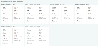
Since the very beginning, one of the rack batteries has appeared to provide the entire EPS standby load being pulled by the inverter. Over the course of a day, battery ID 4 will show intermittent discharge of 0.54A and the SOC % will slowly drop. All other batteries will continue showing 100% status. Batt #4 is installed in slot 4 of the rack. The behavior did not change when I added two more batteries to the system. Batt #4 continues to show all the standby discharge. All connections on the rack bus and battery terminals have been properly torqued. And the bus connections for batt #4 were even moved and re-torqued when the last two units were added at the bottom of the cabinet. I've also tried rearranging comm cables and changing assigned battery numbers, but the discharging behavior remained with the physical unit in slot 4 and not with logical Batt #4.
While the system is in backup standby I have seen the SOC disparity grow as large as about 20%:
Batt1 100%
Batt2 100%
Batt3 100%
Batt4 80%
Batt5 100%
Batt6 100%
I expect it will grow larger but I don’t have enough time with the system yet to have observed that. During significant discharge, i.e. when powering house loads, all batteries share the load and indicate roughly the same discharge current. During charging, all units indicate roughly the same charging current.
As detailed in another thread, during a charging test using the Chargeverter rather than the 18Kpv, I observed that each of the 100% units received about 27 Ah of charging energy. The “low” unit, which started at 88% for this charging test, received about the same amount.
Questions
- What is the expected EPS standby current load on this battery bank from the 18Kpv? Is it a continuous value, or is there a switching function? I ask this because I typically see Batt4 status on the LCD panel alternate between Standby and Discharging. When discharging it is usually showing 0.54A current. The alternating modes seems to be random, sometimes as frequently as 5 sec, sometimes the display remains in Standby for a minute or more. All other batteries show Standby constantly and remain at 100%. Is it possible that all six batteries are contributing to the EPS standby load, but only one of them is sensitive enough to measure and indicate this current draw?
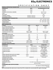
- What is the discharge current measurement threshold for the LL-S BMS? I have encountered other LiFePO4 battery brands that have a relatively high threshold for the discharge current used to calculate SOC. There is one brand that does not include any discharge current below 1.0A in its SOC calculations, according to their engineering department, and so that battery can slowly discharge but will continue to report 100% SOC. Is it possible that my LL-S batteries are each slowly discharging at something less than 0.5A due to the inverter’s continuous EPS standby current load, and the batteries (all but one) are not changing the SOC value from 100% because the current is below some threshold?
Note that all six batteries, at any given time, show almost exactly the same individual cell voltages, regardless of the SOC disparity.


