EG4 Community Forum

GFCI/AFCI breakers ...
 
Notifications
Clear all

Question GFCI/AFCI breakers fail self-test when running from inverter only

8 Posts
2 Users
0 Reactions
143 Views
Posts: 5
Topic starter
(@jsaginaw)
Active Member
Joined: 4 weeks ago

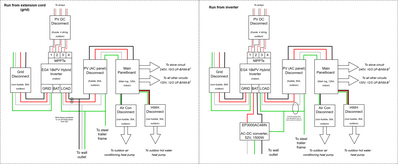
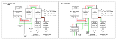
Hi All - bit of a unique situation here. I am building a tiny house at a "construction site" (warehouse) and I have the 18kPV installed and all the wiring before and after my panel is complete. I do not have solar or batteries installed, yet. This warehouse only has single phase 120 readily available, so to test my electronics I have been paralleling the two legs of the panel and running my 120 circuits with no issue. This is shown in the diagram as "Run from extension cord (grid)". I really wanted to test the inverter and run my hot water heater heat pump so I bought a 52V AC-DC power supply to act as a "battery" and run the inverter from. This is shown in the diagram as "Run from inverter" and all worked great! I was able to commission the inverter and my leg voltages look good, and ran ~1kW through it for the hot water heater. However, my 120 breakers are all combo GFCI/AFCI (Eaton CUTCHFP120DF) and after I start running the panel through the inverter, they all click off after 3-5 minutes (not all at once) and give me a 6-light error code which means the breaker failed an "internal self test". When I revert to extension cord power, the breakers are fine, indicating to me they are not permanently damaged. The fact that the breakers are ok in extension cord mode also leads me to believe that all the branch circuit wiring is fine and there are no actual faults within it. 

To note:

  • I received a VBUS over range error once but I am not sure under what circumstances and I cannot find any link between that and the occurrence of the breaker issue
  • My 240 GFCI only breakers (ex: to run the hot water heat pump) do not trip and do not have the self test issue, leading me to believe it is an issue with the AFCI self test feature

My leading hypotheses:

  • Ground-neutral bonding issue (though I did try different bonding conditions)
  • The inverter AC waveform has some harmonics in it or is distorted just enough that the electronics in the breakers can't operate on it

Next tests to try:

  • Run from 48V battery instead of power supply (to rule out ground-neutral issues)
  • Bus capacitance added to the output? Investigate AC waveform cleanliness
  • Firmware update (I have not updated after unboxing in November 2024)

Can anyone speak to this issue or offer some hypotheses and/or solutions?

250324   Electrical Architecture.drawio
7 Replies
Posts: 11
(@fkitzmann)
Active Member
Joined: 2 months ago

Looks like you are supplying temporary power to the inverters load connection (output). Not recommended and possible damage to inverter.

This is ok for testing everything down stream from the inverter as long as the inverters load connection is temporary removed (disconnected). I'm not surprised that the inverter is complaining of a VBUS error. Normally power gets applied to the Grid input connection and is a 240V split phase connection (dual 120V connection which is 180 degrees phase difference). I would recommend using a 240VAC circuit with both neutral and ground (4 wires) for testing. It could be possible to just connect one phase of 120VAC to one power leg of the inverters grid input but I don't know how the inverter will react to just being supplied with one leg (120V) of the 240VAC input circuit. It also may not like being supplied 120VAC to the two input legs (tied together) since it won't be a true 240V split phase input. Also, neutral bonding needs to be done at the grid disconnect switch (first point of entry) if not already done at some place prior. If needed, this should be done at inverter side of the switch since it still needs to be active (connected) even if there is no grid connection.

Reply
Posts: 5
Topic starter
(@jsaginaw)
Active Member
Joined: 4 weeks ago

Ok wait let's back it up for a second - at no point are these modes of operation occurring simultaneously - either the inverter LOAD breaker is OFF and the inverter is OFF and the panel is run from the grid (with the two phases paralleled) and the breakers are fine OR the inverter is run from the power supply, grid is disconnected, phases are not paralleled, and the breakers fail self test. I've updated my diagram for clarity.

Additionally, as mentioned, I do not have access to 240V split phase otherwise I'd use that.

Noted on neutral bonding when that gets setup in the final implementation.

250331   Electrical Architecture clarified
Reply
Posts: 11
(@fkitzmann)
Active Member
Joined: 2 months ago

Ok, now I understand more of what you are trying to do. As far as the breakers tripping goes. Is there a way to determine from these breakers wither they are tripping from a GFI or an AFI event? Error code? Are any breakers wired into a no load circuit? If so, do any of those trip? One way to possibly find out if its tripping because of an AFI event is to disconnect any load wiring from the breakers output and with the breaker turned on, see if it still trips on it's own. Doing this should eliminate any GFI type tripping. If it does trip, then the breaker most likely is tripping because it thinks there is a AFI event. This could be caused possibly by the output waveform produced by the inverter, i.e. some high frequency switching harmonics that is making it past the inverters output stage filtering and the breaker is too sensitive for this type of event (noise). I have not looked the 18KPV's output with a scope so I can't say for sure that this could be your problem, but it's suspect. On another note. On your 52V battery substitution supply. If you have a scope, make sure that it's a stable source of 52V (48V) power. Or just try a battery at this point. Also try all your breakers with no loads connected. Do they now trip more often or less. More then likely it's possible that you won't be able to use this type of breaker (GFI/AFI) with this or any inverter. Typically inverters like these rely on high frequency switching to develop a sign wave, waveform. Then the output of that goes through an output filter. There may be some residual noise left on the AC output which may be affecting these breakers you are using. You could also just try say a GFI only breaker in one location just as a test.

Reply
Posts: 5
Topic starter
(@jsaginaw)
Active Member
Joined: 4 weeks ago

I think it is an AFI self-test feature as I have a 240 GCI only breaker that is stable and does not trip - leading me to the same hypothesis that you have on output harmonics/distorted output waveform. Some breakers are on no load circuits and have the same issue at roughly the same rate as the loaded ones.

Do we know anything about the output filter on the 18kPV? Maybe it could benefit from more capacitance? 

I'll try and work on getting a scope to look at both DC input and AC output to the inverter

Reply
Page 1 / 2
Share: