So I purchased a Eaton BRN115A1CS breaker which supports AFCI and GFCI functions. Not quite what you are using but should be representative of what you have. Will be running some tests with my 18KPV to see how it reacts. On another thought and something you can try in the mean time. I suppose that it could be possible that there could be some type of interference with one of the loads you have connected. To make sure that this is not the case. First pick a breaker that tends to exhibit the issue most often. Then turn off all other load breakers and run with just the one breaker. Does it still trip? If so, remove the load connections (Hot & Neutral) to this test breaker. Reset breaker and try again. Does it still trip on it's own? Also, make sure that your loads neutral connection is from the breaker and not the neutral buss bar connection in the breaker box. These breakers must monitor the currents through the neutral wire through the breaker to operate properly. I'm assuming that you also have the white neutral pig tail wire that comes out of the breaker, is connected to the neutral buss bar connection in the breaker box. One other note. On your ground neutral bonding. This should only take place at one location. Usually at the service entrance, so when you are running from the grid (extension cord), this bonding has already occurred in the buildings entry wiring. So you don't want to have a secondary bonding in your setup in this case. The reverse of this is when you are running solely with the inverter (no extension cord), In which case, you will need to provide bonding in your local PV AC panel disconnect. So this could be an issue if you are trying to switch between the two sources of power, i.e having remote grid power provide the bonding or having to add local bonding when when running on the inverter only and grid power connection is removed.
I did some troubleshooting with an oscilloscope and have some interesting results.
Here is a summarized test matrix and results:
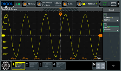
- Run from wall (extension cord) --> waveform looks ok, breakers won't trip no matter what combination of loads is on
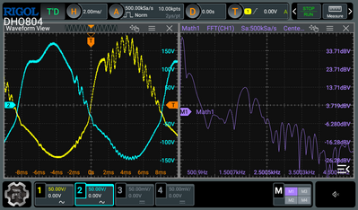
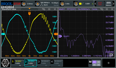
- Run from inverter, low load (150W) --> waveform looks AWFUL, a bunch of high frequency harmonics near the peaks. The breakers will eventually all trip off with the same "self-test" error code. Turning on LED lights seems to push them over the edge but they will trip lights or no lights eventually. During this portion I also received a VBUS OverRange Error. My hunch is that those harmonics are exceeding the internal VBUS limits, but I'm not sure. I was running an FFT on the scope and there is the peak at 60Hz but also smaller peaks at ~2kHz and likely the first harmonic of that at ~4kHz
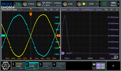
- Run from inverter, more load (~1000W) --> I loaded up the inverter using the heat pump and those harmonics went away, the waveform clears up, and the breakers were happy and didn't click off (across the 20 minute test or so). No VBUS OverRange error either
I received some motor-run capacitors I am going to try and parallel into the output to see if that helps. My hypothesis is that this could just be "loading up" the inverter in the low load cases with reactive current which could help.
My batteries are coming next week but have a few more weeks of commissioning before I can get them working, at which point I'll run another test and see what happens.
Sounds like the inverter always needs a small load. Although you may not be able to count on having some load.
Is this showing both phases? Which phase has the most loading? Yellow?
Seems like the higher frequency noise you are seeing on your waveform is from the high frequencies used to generate the waveform itself and this is enough to get past the internal LC filtering. There could be some issues with the loop response that is responsible for controlling both the end line frequency and voltage. Maybe this loop response can't deal with no or very light load conditions. Is your inverter defective or does this represent all inverters. Hard to say with a sample size of one. Could software fix this? Possibly if the hardware could support the change.
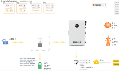
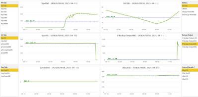
I did run my house on batteries only with the AFCI/GFCI breaker I have described above. Have not see my breaker trip but I'm pretty sure that it's not going to trip with the loads i have. I have not tried to run with no loads and I have not looked at my inverter waveform yet but would suspect that it would be similar to your measurements. If this helps, some actual monitor data info that I have while running without grid -
You can see that I have loads going to support battery charging and house loads in this case. Possibly adding battery loads would also fix it.
Again, If you can't fix the breaker tripping then you probably would need to switch to non AFCI breakers. Although I'm puzzled why your are getting a VBUS OverRange Error since i would think that this is an internal measurement to the inverter only and not affected by any loads you have. Adding motor-run capacitors could possibly help but I would suspect that, that alone may not be enough.
- 37 Forums
- 1,004 Topics
- 5,438 Posts
- 5 Online
- 1,565 Members

