@powerup
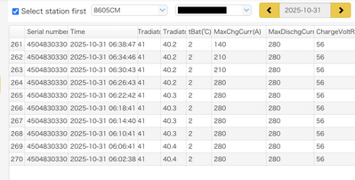
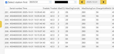
That parameter is not "set" by the user. It is dynamically changed by the master battery to control the rate of charging. This is the primary method of charging control for closed loop operation. The inverter logic decides when to charge, but the master BMS determines how much to charge. It does so by changing the charging voltage and max charging current, but in practice I only ever see the current value change and the voltage is always fixed at 56VDC.
The 28A value represents a charging rate of 0.05C for your system. That's a very slow rate and it means that the BMS thinks that the battery state is nearly full. I see charging current values ranging from 0.5C at the highest to 0.01C at the lowest (that's 300A and 5A respectively, for my system). 0.01C charging for your system should be close to the 350W that you were experiencing. You should review your data history for the times when you saw the lowest charging power (it's the parameter named "pCharge(W)" and then look at the values for MaxChgCurr(A) during those times. If the current value is low, then look at the SOC% value for those times and see if it makes sense. If your BMS is setting a very low charging current value during times when the SOC is not nearly 100%, then you should get Customer Service to help you use the BMS Tools app to figure out why the battery is limiting the charging too much.
FYI, these are the SOC / Charge Current correlation values I have recorded for my system. These were taken at a time when I'm certain the BMS SOC reference was well calibrated. Values are a bit different depending on whether the SOC is on its way up or on its down (charging or discharging), so I've listed both. I'm giving current values in C rates, so you'll need to do the math to get amps for your system.
Discharging
SOC% MaxChgCurr(A)
100 0.01C
99 0.05C
98 0.15C
96 0.25C
94 0.29C ~ 0.46C
93 ~ 0 0.5C
Charging
SOC% MaxChgCurr(A)
39~91 0.5C
92 0.46C
94 0.375C
96 0.29C
97~98 0.15C
99 0.08C
100 0.04C ~ 0.01C


